UC4 - Human-Robot-Interaction in Semi-Automatic Assembly Processes
- Fraunhofer IESE The Fraunhofer IESE is an applied research institute in the area of software and systems engineering. The institute develops innovative solutions for the design and validation of dependable digital ecosystems in the domains of autonomous systems, industrial IoT, smart farming, and health care systems.
- Universidad de Castilla-La Mancha Spanish university created in 1985. It is the flagship higher education institution of the Castilla-La Mancha region. UCLM has four campuses: Albacete, Ciudad Real, Cuenca, and Toledo. It also has university sites in Talavera de la Reina and Almaden.
- Eskisehir Osmangazi University Development of Verification and Validation methods for Safety & Security of industrial robots. The developed methods will also be validated in a TRL-5 laboratory environment in Eskisehir Osmangazi University Intelligent Factory and Robotics Laboratory (ESOGU- IFARLAB, ifarlab.ogu.edu.tr ).
UC4 is based on a Human-Robot-Interaction (HRI) process taking place on the shop floor of a manufacturing-like environment. The process itself involves the execution of assembly tasks by human workers focusing on the assembly of transformer units which consist of multiple parts. HRI systems have to manage the coordination between humans and robots according to the requirements for collaborative industrial robot systems as defined in ISO 10218-2:2011, ISO/TS 15066 (Technical Specification Robots and Robotics - Collaborative Robots), and IEC 61508:2010 (Functional Safety).
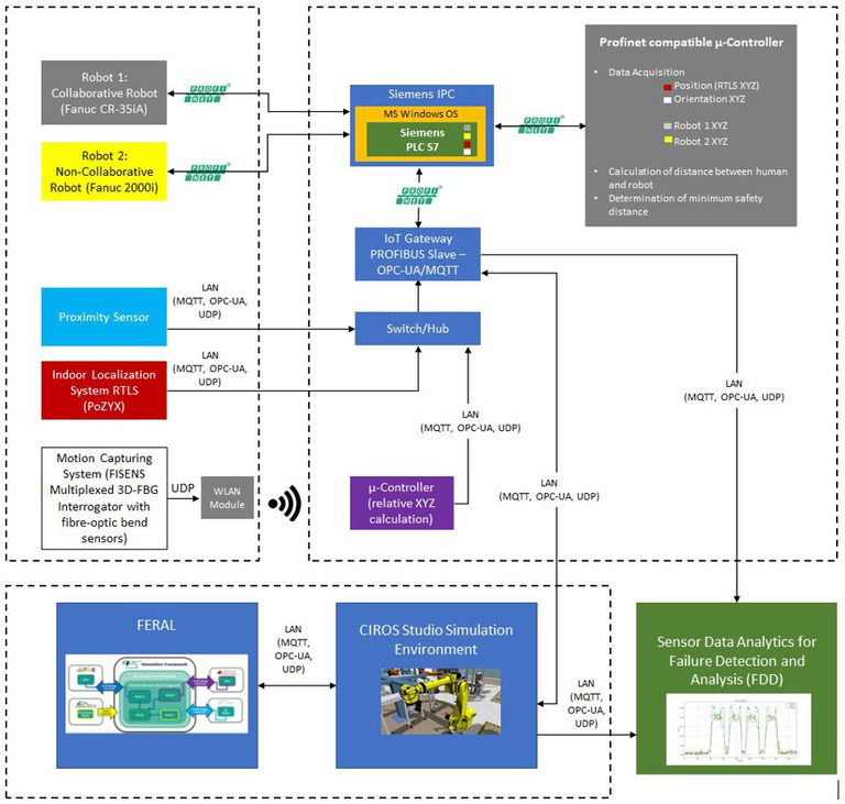
Recognizing and localizing objects of interest and tracking them in the workspace to allow a smooth flow of interaction between human and the robot are of vital importance, particularly in scope of the evaluation and test scenarios for failure injection. The envisaged use case is set up as a physical demonstrator, consisting of different IoT building blocks as sketched in the following figure. These include one six-axis collaborative robot (Fanuc CR35ia) and one six-axis non-collaborative robot for medium payloads (Fanuc R2000i), an IPC (Industrial PC) with a soft-PLC (Siemens S7), an IoT gateway, a switch/hub, and two functional safe microcontrollers for doing the pre-processing of sensor data.

The IoT components responsible for generating the positioning sensor data include a wearable, fibre-optic sensing system and an Ultra-wideband (UWB) based indoor localization system. While the fibre-optic sensor system calculates the orientation of the body limbs (arms, hands, and shoulders) of the human, the localization system localizes the relative position of the human within the workspace. The sensor data streams of both systems are communicated via communication protocols such as UDP, MQTT, and OPC-UA. The communication between the IoT components directly connected to the IPC is performed via PROFINET connection. The corresponding test cases will consider specific failure injection methods in both physical and virtual space as defined in the evaluation scenario spreadsheet.
On a component level, it is planned to focus on the manipulation of data generated by three IoT sensor components, namely from the fibre-optic sensor system, the UWB localization system, and the proximity sensor. Additionally, it is foreseen to inject failures directly in the PLC device. For the full deployment of the HRI use case, a simulation model of the behaviour and interaction of the physical components according to the above figure will be parallelly implemented in CIROS Studio and coupled to FERAL - a simulation framework for virtual validation – via one of the communication protocols such as MQTT or OPC-UA.
The main sensor systems (fibre-optic sensor system and UWB localization system) are not available as virtual models within the preferred simulation environment, thus will therefore be complemented through approaches based on hardware-in-the-loop (HiL), as well as the creation of complementary virtual models through the support of FHG IIS. For the purpose of realising a failure detection and diagnosis as proposed in this use case, it is foreseen to access and analyse the manipulated data streams emerging from the IoT components by implementing a sensor data stream pipeline based on the usage of appropriate data mining and machine learning techniques. The objective here is to detect and classify failures on the cyber-physical level for HRI applications
