UC11 - Automated Robot Inspection Cell for Quality Control of Automotive Body-in-White
- Eskisehir Osmangazi University Development of Verification and Validation methods for Safety & Security of industrial robots. The developed methods will also be validated in a TRL-5 laboratory environment in Eskisehir Osmangazi University Intelligent Factory and Robotics Laboratory (ESOGU- IFARLAB, ifarlab.ogu.edu.tr ).
- PUMACY TECHNOLOGIES AG PUMACY TECHNOLOGIES AG is a leading provider of knowledge and data analytics solutions. Smart service solutions cover the technical, methodical and organisational aspects of data analytics and related context-sensitive solutions. It comprises the employment of cyber-physical systems, industrial IoT components and sensor-based wearable solutions in industrial environments.
- Inovasyon Mühendislik Inovasyon Engineering is a SME located at Eskisehir Osmangazi University Teknopark. Inovasyon Muhendislik was established in 2010 with the support of TUBITAK Teydeb 1508 program. Company conducts R&D projects on indoor and outdoor positioning systems, intelligent vehicles, robotics and machine learning supported by ITEA, ECSEL, Third Party Funding, TUBITAK and KOSGEB. Company realizes embedded system based electronic equipment and system design, development and production on these projects.
- Techy Bilisim Ltd. TECHY is participating the Use Case #11: "Automated robot inspection cell for quality control of automotive body-in-white."
- ERARGE Research Center ERARGE Research Center is the R&D Branch of Ergünler Co. which employs young and experienced researchers. The research team has 3 PHDs, 1 academician, 5 experienced and 5 junior researchers working on hardware and software technologies.
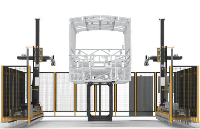
UC11 is developing a new system using new visual inspection techniques to shorten the part existence control time for automotive body-in-white, see Figure 1.1. The baseline of this use case is to provide a better fault-tolerant production system to achieve better quality control.
Controlling the existence of 2500-3000 body parts is planned to be executed fully automatically by cartesian robot and camera sensor system. Using the cad-data of the vehicle, digital twin software developed by OTOKAR, which runs in a server PC, will decide the safe robot trajectory points to check the existence of all parts. For each point stored in the server PC, the software will position the virtual camera in the cad environment and render a virtual 2D image. 2D images will be also stored in the server PC. Processing the trajectory points as an input from the server, the software running in the system PC will control the axis motors via PLC and drivers to position the cartesian robots developed by Otokar in real production environment. For each position camera sensors capture 2D images from the real production environment. Presence-absence check is performed by means of comparing the synthetic 2D image stored in the server and the actual data obtained from the camera system. The quality reports and system status data will be stored in the server PC.
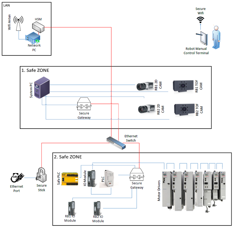
To ensure that VALU3S technology is applicable to the robot inspection cell for quality control, in this use case, we will cover an automated fault and attack injection, specifically for controlling the entire industrial automation line. The existing Quality check processes are still very long and ineffective without advanced safety concepts. Additionally, Quality check in existing manufacturing environment is not very responsive and adaptive to online sensing. It works in Stop & Go mode to provide the safety. In this case, there is a need to increase autonomy of the system by ensuring the safety of the system. Autonomous trajectory generation methods optimized according to time and safety will be developed. In addition, the robotic system will be able to perceive the current state of the environment in real-time and implement a dynamic motion plan by considering the existence of the operator in the environment. The safety of the system will be verified both in the current system and the system developed in the laboratory. The safety requirements will cover the safety of the operator, robot and its apparatus as well as static objects in the workspace. In manual mode human safety will be improved by maintaining secure communication with operator and robotic system, see Figure 1.2 for system topology. Also, it is intended to focus on dependability as a case of safety.
 Figure 1.1: Robot inspection cell for quality control
The use case will be evaluated considering in particular that VALU3S facilitates security and safety by:
- Demonstrating results from simulations and the role of VALU3S in decision making.
- Manipulation of the data that is collected from system components and stored in the automation system
- Manipulation of the data that is transferred from server to system PC
- Observation of the inspection process flow data to detect anomalies in production phases; and regarding software-level attacks
- Anomaly detection at component and system level by utilizing ML and/or deep learning-based techniques.

Figure 1.2: Detailed topology of the system showing data transfer protocols
The VALU3S tool that developed in the project will be first tested in a laboratory environment before implementing in a real environment. It is due that the actual system is actively used in the production process of OTOKAR. Therefore, the experimental system in the laboratory will have a TRL5 level setup before implementing the tools in an operational environment.
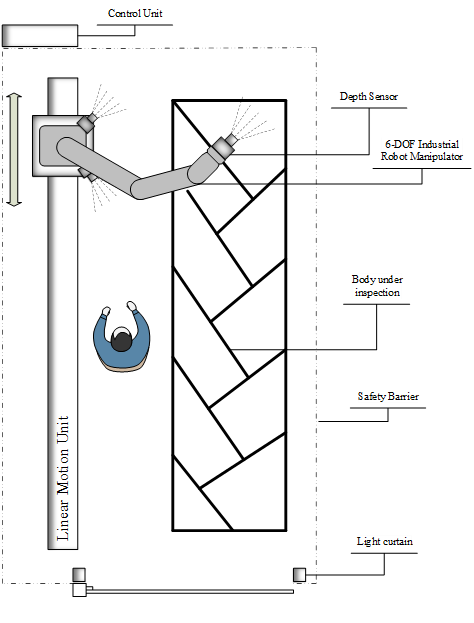
A small-scale experimental system similar to UC11 will be constructed in the laboratory environment at ESOGU Intelligent Factory and Robotic Laboratory. The conceptual design of the experimental system can be seen in Figure 1.3. The robotic inspection system consists of an industrial robot manipulator which is mounted on a linear motion unit. An RGB camera and depth camera will be mounted at the tip of the manipulator. These cameras are used for two purposes. One is to capture data of the body to perform the presence-absence check of the parts. The other purpose of using the cameras is to provide an environment map for the robot allowing it to avoid obstacles. Also, multiple depth cameras that view the workspace from different points of view will be placed in the environment. The data captured from these cameras will be used to provide a periodically updated 3D map of the environment. This map will be used for the safe movement of the robot and the detection of humans entering the workspace. There is also a light curtain in the entrance of the workspace for the detection of entrances to the workspace. Control units consist of all equipment (devices, power units, fuses, system computers, etc.) needed for management of the system.

Some improvements to the existing system will be made for some additional functional requirements. In the improvement phases, V&V methods will also be demonstrated. V&V methods will be performed on both the existing system and the improved system. In both cases, development, tests, and the demonstration of V&V methods are applied primarily to the experimental system.
