UC3 - Radar System for ADAS
Use Case Description
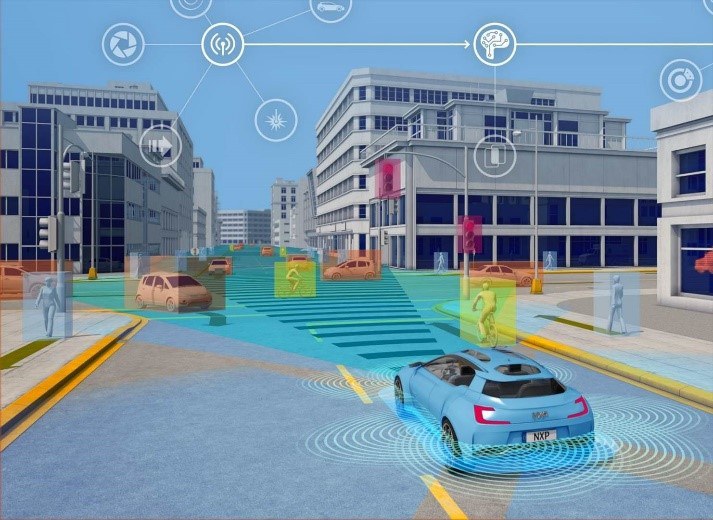
The current trend in the automotive industry for integration of advanced driver assistance systems (ADAS) and developments to even higher levels of automation [2] , is challenging the traditional automotive industry across its entire supply chain, from the IC supplier up to the OEM. ADAS provide the safe and increasingly autonomous experiences that will reshape our relationship to transport. The technologies of the automated driving domain will soon allow passengers a personalized and connected experience as vehicles seamlessly sense, think and act on real-time road situations, see Figure 1.5 for an illustration. While the technical complexity of these systems is rising dramatically to enable the needed functionality in a robust, safe, and reliable fashion, quicker times to market are needed at the same time.

Figure 1.5: Illustration of an automated car in a complex urban scenario
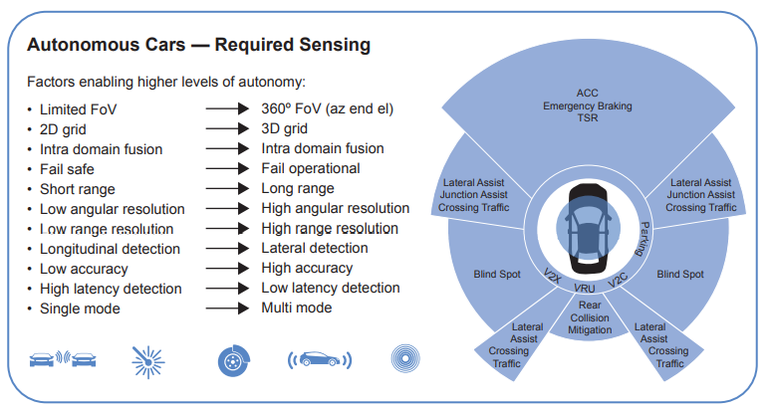
For the foreseeable future, radar and camera sensors will comprise the optimal sensor complement for vehicle safety applications, providing the affordability, reliability and combined functionality needed to enable the next generation of safer, smarter cars, see Figure 1.6 for required sensing for autonomous cars. And while camera sensors are essential for object recognition and classification, radar sensors are immune to camera sensor deficiencies that limit their effectiveness in low light and inclement weather conditions, while providing the high-precision, vehicle-to-object distance, depth and velocity ranging capabilities that cameras cannot.
The radar systems continually sense the distance between vehicles in real-time, improving driving efficiency and safety. NXP, this use case owner has a full portfolio of scalable radar solutions, including highly integrated radar MCUs and transceiver technologies which offer their customers solutions that address USRR[1], SRR[2], MRR[3] and LRR[4] aimed at current applications (such as ADAS Adaptive Cruise Control (ACC), ADAS Crossing Traffic Alert (CTA), ADAS Parking assist, NCAP Automated Emergency Brake (AEB), NCAP Blind Spot Detection (BSD), and Corner Radar) and future radar applications.

Figure 1.6: Required sensing in autonomous cars (Source NXP [3])
This VALU3S use case “Radar system for ADAS” looks at these challenges from the perspective verification and validation domain of the ADAS IC manufacturer. Due to the higher complexity of these modern ADAS systems to be developed, there are challenges that cannot be addressed with the traditional V&V method.
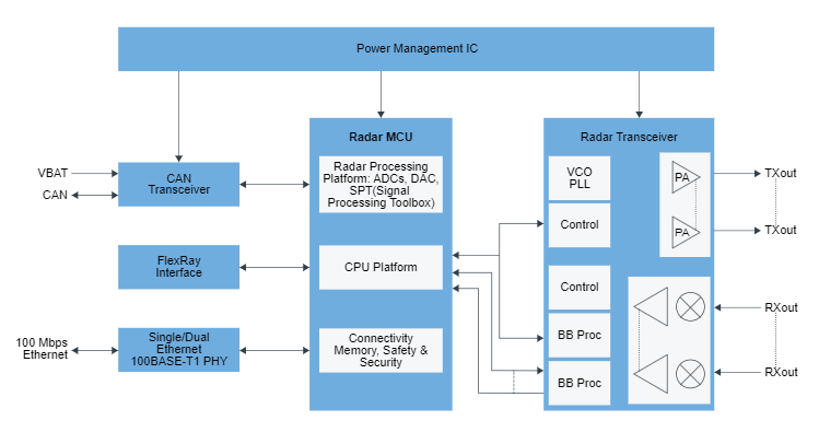
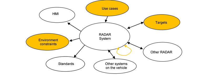
One of the challenges to be addressed is the necessity to include the verification and validation at system level, see Figure 1.7, from the design to the production of the IC components. This must be done to include the interaction between the semiconductors and all the peripherals, see Figure 1.8, around the sensor to grant the safety and the reliability of the final system.

Figure 1.7: High level view of a radar system (Source NXP [4])

Figure 1.8: Radar System verification & validation with focus on use cases, targets and environment constraints
Although NXP is an IC supplier in the value chain, by performing validation at system level, problems at Tier 1 level (sensor and sensor system developers) can be foreseen and solved before they appear in a much later development stage (resulting in longer time to market and much higher sensor development costs). Performing validation on system level as an IC supplier is hence resulting in a shorter time to market, adding value proposition to the customers and reducing development costs. The VALU3S project will be used as a framework to extend the V&V method and to introduce new validation strategies at system level with a special focus on the IC development. In this way, the performance of the final integrated sensor can be granted from the perspective of the IC development.
Another aspect in the project is the fact that the future radar chips will integrate the processing chain and the transceiver in one system on chip (SoC). In the past, to validate the transceiver, costly equipment had to be used. With the integration of the processing chain, design for test techniques can be integrated into the system adding test capabilities that can be used by validation and production lowering the testing costs, time, and validation effort.
As NXP main focus is the design and production of IC for automotive radar, the system validation will focus on the IC level and not on the radar product level so not all the processing chain and hardware will be part of the system Validation. The Tier1 validation including field test, road data collection etc. has to constraint to Lab condition. As part of the new V&V method, it is planned to place a radar system in an anechoic chamber in front of a target simulator in order to simulate real test use cases. Consequently, the scope of the system validation differences from the Tier1 scope or OEM and will be only a subset of these use cases used by them. This is due to limitation of the test bench as state of the art of radar target simulator can’t generate infinite of targets. Moreover, the bench will generate a single point target and not multireflection target as a real environment.
Due to the simplicity of the radar target simulator scenarios and in order to feed the gap with the Tier1 and OEM approach, more complex and realistic scenarios will be simulated, and environmental data will be injected to the processing chain. Ray tracing technics will be used to simulate these data. Because of the complexity of the system and the interaction between hardware and software, a multistep approach is used to validate and debug the system so different level of Hardware in the Loop test will be performed. The full automation of these benches and moving field tests to the lab allow cheaper and faster validation phase for NXP IC.
[1] Ultra short range radar
[2] Short range radar
[3] Mid-range radar
[4] Long range radar
