Coordination of Test Generation and Validation in simulation based Human Robot Collaborative environments workflow
The ULISES framework transforms data streams generated by a Virtual Reality Interactive System into data suitable to diagnose a test case in real time. This diagnosis will generate sufficient information to validate a test case specification.
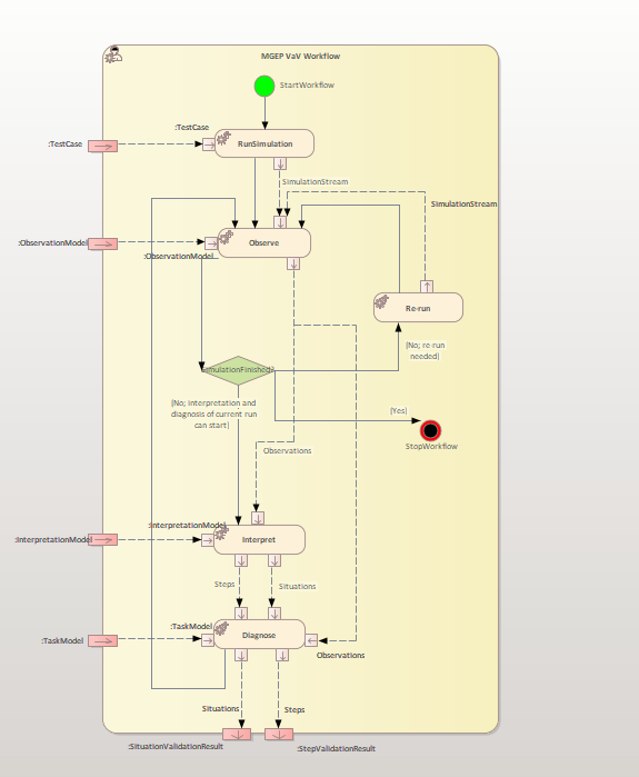
ULISES is a three-layered framework that explicitly models the unconscious process that a real human use when they supervise real activities: they first perceive the environment through their senses, then they interpret what is happening and lastly they make a diagnosis about what happened. In order to ensure that the runtime kernel is able to observe, interpret and diagnose students’ activity, the ULISES framework defines the ULISES metamodel, which is divided into three abstraction levels and each of them generically describes a set of elements that have to be particularized into the Task, Interpretation and Observation Models. In other words, the metamodel defines elements to specify how to observe the actions that are being carried out in the Interactive System, how to interpret the steps taken by user or robots and the context in which they are taken, and how to diagnose them. Hence, each level of the metamodel represents a different phase in the task creation process.

.png")
The core unit of this level is observation, which represents an event or a fact taking place during an interval of time in the simulation. Therefore, the Observation level contains generic elements that specify how the data streams coming from the IS must be transformed into single meaningful entities (observations) that describe something perceived during an interval of time. Taking a driving simulator as an example, the driver perceives certain elements during different periods of time: the intersection he is approaching, the vehicle on his left, the solid line on the road, and so on. These observations will be used as primitives for describing students’ activity on the other two levels: interpretation and diagnosis. For example, if overtaking (which is a durative action) needs to be described in the interpretation level, first the movements to other lanes and the movement of the preceding vehicle need to be observed. Additionally, observation properties can be defined. For example, the “Preceding vehicle” observation would have a “Distance” property that would register the change in the distance to the preceding vehicle during the interval of time when it is observed.
Allowing both discrete and continuous input is a crucial advantage at this level. Thus, both continuous observations, e.g. the driver is approaching the left lane, and instantaneous observations, e.g. the driver is pushing a button, can be defined. The observation model defines for every observation its properties, the input data (from any source) needed to generate the observation and its properties, and the ULISES Observer plugin, which processes the input data. With this model, the ULISES runtime kernel fuses the inputs from the simulation and updates in real time the set of synchronized observations that are perceived. This means that after every update cycle new observations are perceived, other observations are completed and still other observations continue with updated properties. Then, the interpretation subsystem is notified in order to perform its own interpretation cycle.
The interpretation level generically describes how to recognize human or robots’ activity in the simulation, that is, it expresses digitally what is happening in the virtual environment. Just as instructors make subjective interpretations based on what they perceive, ULISES does the same when interpreting the observations from the IS. The interpretations shall be valid and complete enough so that the ULISES diagnosis subsystem can determine whether actions in the test case are valid or not. Therefore, the interpretation subsystem must recognize the actions performed by the different simulation elements and the context in which the actions are being carried out. For this reason, the interpretation level specifies how the interpretation subsystem must interpret two core elements from observations: steps and situations.
· Step: This represents an action that takes place over an interval of time and that will be diagnosed. The step model contains the necessary attributes for the ULISES runtime kernel to interpret when a step is being performed from observations. It is important to emphasize that the observations contained in the step model cannot depend on the correctness or incorrectness of the step. For example, in a driving context, if an “overtaking” step is modelled, the observation where the vehicle is in the left lane should not be included. The driver could be overtaking from the right, incorrectly, but still overtaking. Determining correctness happens at the diagnostic level rather than at the interpretation level.
· Situation: The term context has many definitions, but all of them underline the importance of the context when interpreting or diagnosing an activity. A situation represents a context that is relevant for diagnosing where some steps will be performed. We identify specific situations when there is a set of factors that determines the steps that students must perform. For example, driving on the highway at 100 km/h is not the same as driving at the same speed on a city street. The student is performing the same step, but it has a different meaning in each situation.
The diagnosis level contains the elements that have to be particularized in order to generate the task model. This model describes the tasks that simulation elements are to perform so they can be diagnosed automatically. In order to define the composition of a task and its validation, the diagnosis level defines the following elements:
· Step: This represents the minimum diagnosable unit.
· Situation: This represents the diagnosis context. It includes the specification of possible solutions to the situation and the information (observations) that will be necessary to diagnose the steps executed.
· Solution: A solution defines if a specific task is valid within a situation. Each solution can be linked to a different diagnosis module, so multiple diagnosis techniques can be used at the same time for different solutions. Nevertheless, the solution must always be composed of steps, although the specific structure depends on the diagnosis technique that is used.
Due to the domains where the system will be validated, we chose to implement a constraint satisfaction based diagnosis technique. Within this technique, constraints are used as an element to restrict whether a step is correct or incorrect in the solution specification. Rather than defining a way to solve a problem, constraints allow for the definition of how certain actions should be solved in order to detect mistakes. Thus, if a constraint rule is not satisfied, a mistake is detected. The advantage of constraint-based modelling is that it is possible to group actions that violate the same domain principle. In our case, we go further and define solutions over situations and steps. We group actions that violate the same domain principles, but at the same time, we are able to distinguish the context in which the mistake was committed. This distinction is very important, because there are many cases where the same error can have a different meaning.